Go-Around-Joe
Visual Glideslope and Go-Around IndicatorThe Go-Around-Joe is a Visual Glideslope and Go-Around Indicator, designed predominantly for GA (general aviation) aircraft flying by VFR (Visual Flight Rules).
Go-Around-Joe Visual Glideslope and Go-Around Indicator
Existing VFR glideslope indicators are typically expensive, complicated to install, and require electricity to operate.
The Go-Around-Joe was developed to provide pilots flying VFR into challenging airfields with an easy means of establishing the required glideslope, thereby avoiding any obstacles on approach and maximising available runway usage.
The lightweight aluminium structure is erected roughly 10 – 15m off the centreline of a runway, and is set to provide the pilot with the optimal glideslope for the airfield.
The Go-Around-Joe is NOT intended to take away from the PIC the responsibility for setting up the aircraft on the required glideslope. Rather, the Go-Around-Joe is there to provide the PIC with VERIFICATION of the preferred glideslope in order to clear any obstacles on final approach and to land as close to the threshold as possible.

View of the Go-Around-Joe from 500m
This is a must-have. The Go-Around-Joe is really impressive, taking all the guesswork out of one of the most critical decisions in aviation: To land, or not to land.
Possible Use Case: NO-GO-AROUND Airfields
Go-Around-Joe Use Cases
- Training Airfields
- Complicated Approaches
- Obstacles on Approach
- Glider Airfields (where there is only one chance to land)
- Short Airfields where ‘Landing on the Numbers’ is a Requirement
- Forward Military Air Bases
- Airfields without Go-Around Options (mountains or other obstacles)
- Steeply Inclining or Declining Runways in which the geometric view / \ is compromised
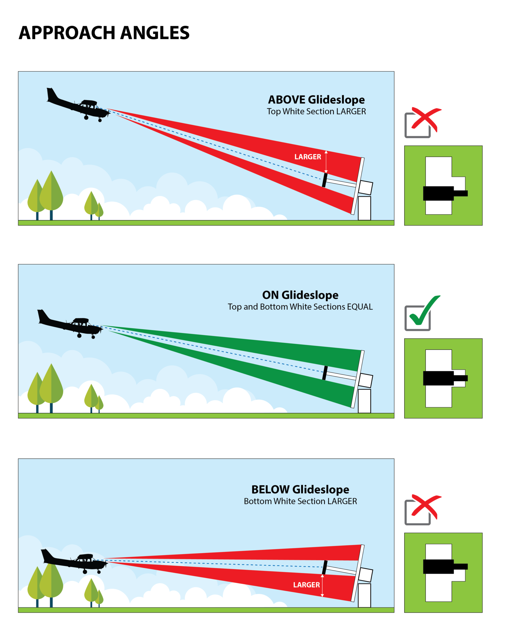
How the Go-Around-Joe Works
The following is an illustration of how the Go-Around-Joe works, showing the various perspectives presented to a pilot, depending on the aircraft’s position on approaching a landing.

How the pilot would interpret the image of the Go-Around-Joe
(click on images to enlarge)
Landing Sequence using the Go-Around-Joe
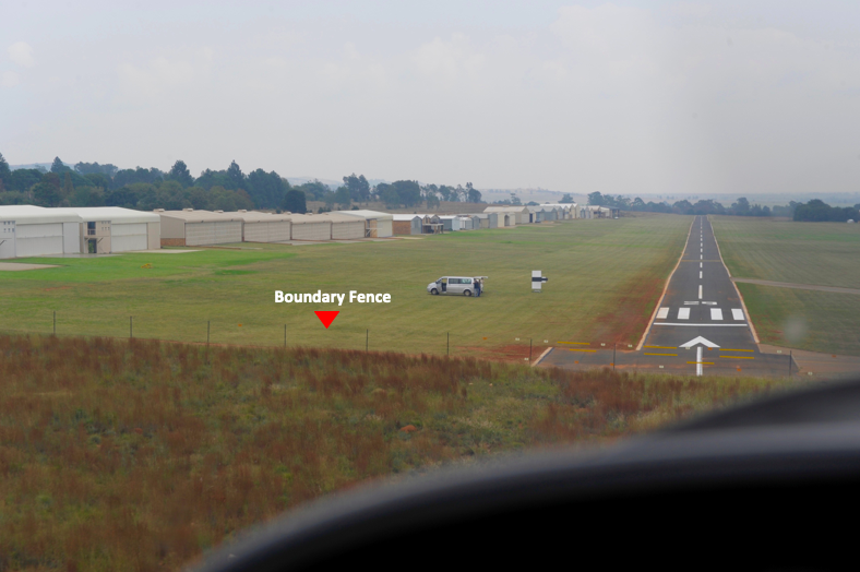
The following is a landing sequence using the Go-Around-Joe. Notice the boundary fence right at the threshold.
The Go-Around-Joe is visible from 1,500m.
In the last photo in the sequence it is evident that the pilot and aircraft are slightly below the recommended glideslope, indicated by there being more white visible below the black bar than above, suggesting the need for a possible go-around.

Image Gallery


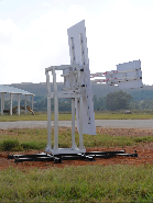


Note: Certain of the photos in the gallery show the Go-Around-Joe on a temporary steel base, whereas the final installation would be on a concrete foundation.
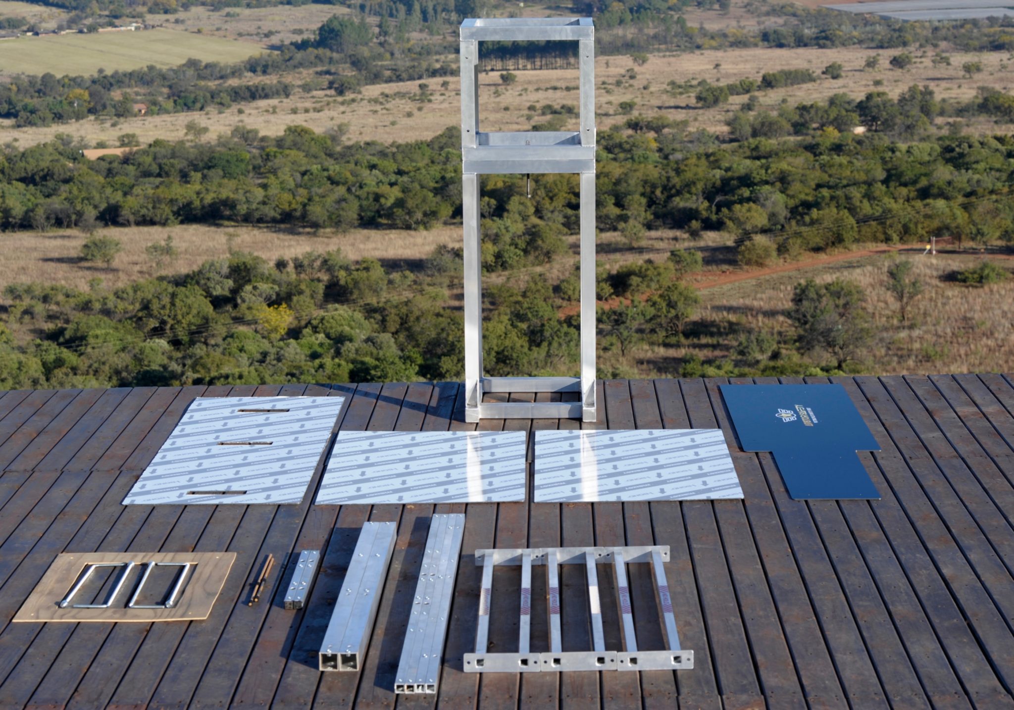
Go-Around-Joe Installation
Installation of the Go-Around-Joe is fairly simple and can be undertaken by a builder qualified in concrete work and setting levels.
The glideslope angle ranges between 3 and 6 degrees, and is calculated according to obstacles needed to clear. The purchaser is responsible for ensuring the glideslope angle is correctly calculated and maintained.
A detailed installation guide is included with every unit shipped.
Click the IMAGE for the Foundation Guide
Click the IMAGE for the Installation Guide
Glideslope Calculator
Click on the image below to download the glideslope calculator to assist with the calculations when installing the Go-Around-Joe:

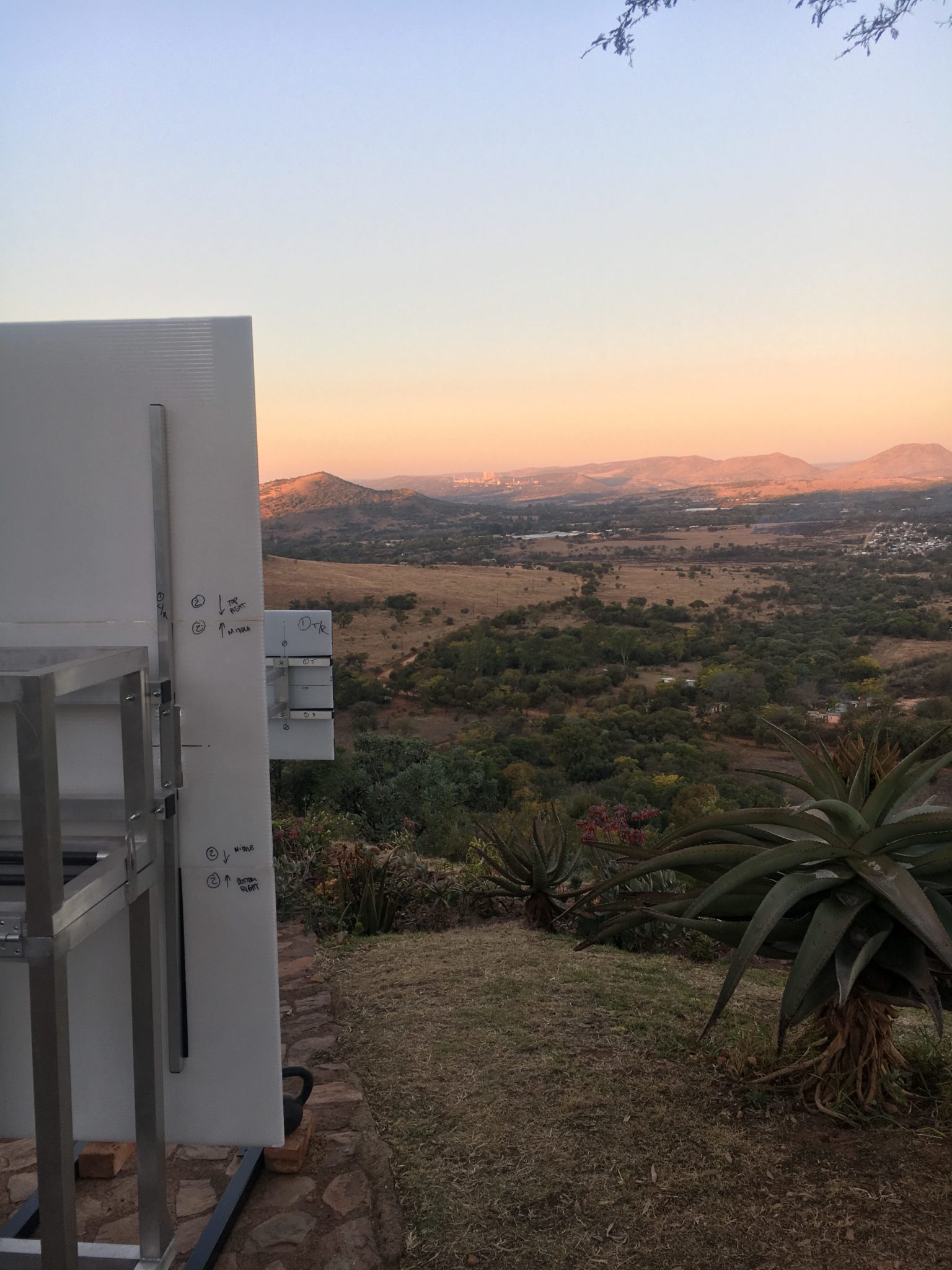
Macro & Micro Indicators
The Go-Around-Joe has TWO elements:
On the LEFT-hand side is the MACRO element, which is visible from 1,500m.
On the RIGHT-hand side is the MICRO element, which enables the pilot, when closer, to better assess the aircraft’s vertical alignment with the glideslope.
Visibility Testing of the Go-Around-Joe
In order to verify the visibility of the Go-Around-Joe, we engaged the services of a specialist optician, who calculated that the 2m high white board with the large black 600mm panel across the middle should be visible to a person with normal eyesight from at least 1,300m.
Beyond that, we conducted ‘land-based’ visibility testing, with both pilots and non-pilots, the results of which were that the Go-Around-Joe was visible from as far as 1,600m.


Clearing Obstacles on Final Approach
Many accidents have occurred through misjudging the approach glideslope, particularly when there are obstacles to clear.
With Go-Around-Joe
Without Go-Around-Joe


Case Study: High-Wing and Low-Wing Aircraft on Same Approach but Differing Glideslopes
In this video, a high-wing aircraft and a low-wing aircraft both on the same approach but differing glideslopes almost collide. Had they been on the same glideslope, this ‘near-miss’ would never have occured. Watch for yourself . . .
Case Study: Tragedy as Two Aircraft Converge on Disparate Glidesopes
In this video, similar to the one above, two aircraft both on the same approach but differing glideslopes, yet these two collide. Had they been on the same glideslope, this tragedy would never have occurred. Watch for yourself . . .
Case Study: Cables on Approach
In this video, a pilot misjudges his approach and/or is unaware of the cables on approach. Watch for yourself . . .
Case Study: Too High on Approach (Landing too Deep)
In this video, the founder of AV8TOR SAFETY was flying an approach on a short, grassy and wet runway and misjudged the approach. Keeping the approach too high over the trees at the threshold resulted in landing halfway down the runway. The result was the inability to brake in the distance remaining. Watch for yourself . . .
Good Enough for Naval Aviators - Good Enough for GA Pilots
Although the Go-Around-Joe was invented and developed completely from scratch and without consideration of aircraft carrier landing systems, it is nevertheless extremely interesting to see the similarity between the simple technology in the Go-Around-Joe versus the complex array of lights in the Fresnel Lens Optical Landing System (affectionately referred to as the ‘Meatball’) used on aircraft carriers. The infamous saying, “On-the-Ball”, comes from the Landing Signal (or ‘Meatball’) Operator, when verifying the correct glideslope and alignment of an aircraft on ‘short finals’ for a carrier landing.

Above: The Fresnel Lens Optical Landing System as deployed on the deck of an aircraft carrier.
Right: A land-based version of the Fresnel Lens Optical Landing System being used for naval aviator pilot training.

Whereas the Fresnel Lens Optical Landing System has provided a GLIDESLOPE CHECK for hundreds of thousands of carrier landings by highly experienced naval aviators, GA pilots today, outside of the airports with ILS, PAPI, and VASI visual glideslope landing systems, have no means of verifying that the glideslope they are flying is correct, particularly when flying into complicated airfields, including those with obstacles on the approach.
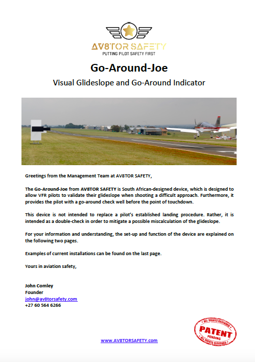
Download Brochure
Click on the image below to download the Go-Around-Joe brochure.
Purchase and Terms & Conditions of Sale
INCOTERMS are ‘Ex-Works’ (South Africa).
Contact us for Pricing and for the Terms and Conditions of Sale